Instead of purchasing the bare chips for pennies at LCSC and putting together a breakout board, I bought a couple modules from Electrodragon. I had learned that the CH551, CH552, and CH554 all used the same die. I bought the CH551 and CH552 modules with the intention of eventually trying to hack them into working as a CH554.
For testing the modules, in addition to the CH554 SDK for SDCC on Linux, I've used Ch55xduino on Windows. One thing not in the Ch55xduino documentation is driver setup. The windoze version I'm using is 7E, and when I first inserted the CH551 module, I got a driver error.

Using Zadig to set the driver to libusb-win32 solved the problem.
The CH55xduino documenation also lacks pinout documentation for anything other than the reverence board. To help, I've copied the pinouts from the CH552 datahseet.

The CH55x bootloader supports DFU, which is what the CH55xduino uploader uses the first time code is uploaded to the module. Once the first sketch is uploaded, the CH55xduino core includes a CDC serial stack. With my CH551 module no longer appearing as a DFU device, I had to use Zadig again to change the CDC Serial device to use the USB Serial (CDC) driver. After that, the module appears as a COM port.
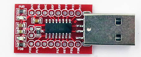
With the COM port selected in the Arduino IDE, subsequent uploads enter the bootloader by switching the baud rate to 1200bps. If no COM port is selected, the upload tool looks for a CH55x device in DFU bootloader mode. To enter the bootloader, it is necessary to pull the USB D+ pin up to 3.3V when power is applied. The Electrodragon boards have a pinout for an upload jumper, which when shorted will connect the D+ pin (P3.6/UDP)to 3.3V through a 10k resistor. On one of my modules I soldered pin headers and use a jumper to force it into upload mode. On the other, I just used a low-value (270Ohm) through-hole resistor pushed into the holes.
Currently CH55xduino is not optimized for size, with a basic blink sketch requiring 5333 bytes of flash. Officially, the CH551 is only supposed to have 10kB of available flash, so the CH55xduino overhead means less than 5kB is left for user code. The CH551 actually seems to have 12kB available for flashing user code, which I think will be plenty if the CH55xduino core gets some optimization work. Since I like to do low-level embedded coding, I'll be using SDCC from the command line most of the time. The blink example in the CH554 SDK for SDCC compiles to 700 bytes, and I was able to get that down to 232 bytes after leaving out the UART initialization in debug.c. With a bit more optimization I think I can get the blink example down to 100 bytes or so.
One small surprise I found during my testing is that the Electrodragon CH551 and CH552 modules use different pins for the user LED. On the CH551, use P3.0, working in open-drain mode so the LED light up when P3.0 is low. On the CH552, drive P1.4 high to light the LED. This is documented on the Electrodragon web site, but it is easy to forget when switching between the two modules.
I've already started to learn how to configure the standard MCS-51 UART, and have figured out how to directly manipulate the ports using the SFRs (Special Function Registers). Once I've mastered how to program these cheap little devices, I'll follow up with another blog post revealing the details.
Postscript
I recently found out that these modules do not fit well in a solderless breadboard. The row spacing for the 0.1" headers on the CH551 is about 0.47", so the pins have to bend out slightly to plug into the breadboard. On the CH552 module, the row spacing is about 0.52", so the pins have to bend out slightly to fit.
Thanks for this post. I will be giving it a shot soon. I'm interested in using the ADC's of this unit.
ReplyDeleteThe ADC is disabled on the CH551, so you'll need a 552 or 554.
DeleteHi thanks for sharing, did you get the UART working?
ReplyDeleteYes, I was able to run the usb CDC example on my CH552. It uses the 2nd UART which is not enabled on the CH551. I may change it so it uses the first (standard 8051) UART instead.
Deletehttps://github.com/nerdralph/ch554_sdcc/tree/master/examples/usb_device_cdc
This is a great posting, thanks for your contribution...
ReplyDeleteLove it. I'm gonna order a reel of these and play. I envision making usb converterz to adapt vintage hardware to usb and vice versa. First project that springs to mind is a usb to adc adapter, so i can use a moxern keyboard on my apple iigs.
ReplyDeleteI just posted a new article I think you'll also enjoy.
Deletehttp://nerdralph.blogspot.com/2021/01/quirks-of-ch55x-mcus.html
Thanks for your work documenting your experiences with these chips. They've been a great guide.
DeleteOne thing that I've found is that new devices have a new version of the bootloader, and librech551 doesn't work with it. However, VNPro (that's bundled with CH55xduino) and a handful of other tools do.
I noticed the most recent batch I received in late 2020 came with bootloader v2.4. I've been using ch55xtool under Windoze and Linux for several months now and find it works very well.
Deletehttps://github.com/MarsTechHAN/ch552tool
I bought a tang nano board with the CH552T on it, and I have severe problems using the serial port connected onboard. I wanted to do similar to this https://github.com/kingyoPiyo/Tang-Nano_I2C_Monitor but cant make it talk serial (putty). Apparently putty hangs when it wants to trasmit, and does not show anything received. Any clues anyone?
ReplyDeleteWhen trying to upload usb_jtag.bin using rather new WCHISP(V3.2), I get the error
ReplyDelete"Jump to BOOT from the user area, configuration bits cannot be modified!"
Followed by
"BTVER:02.40"
"UID:...."
"Unable to revamp CfgBit when entrance BOOT without power on"..
Im not sure what this means.. I used FT_Prog to put it in boot mode. Do I need to add a continuous pullup to P3.1?
Am able to program CH552 using the WCHISPStudio software without a problem but CH554 is not recognized despite using the wiring shown at https://i.stack.imgur/D4grM.jpg. Have adjusted the pin connections to account for the different CH554 pinout. Anyone have a suggestion for a circuit to program the CH554? Perhaps using the serial port in place of USB.
ReplyDeleteThat URL is invalid. Updated bootloader IDs have caused problems in the past, so that is one idea. I've never used the CH554, so I'm just guessing.
DeleteHi, Anyone have sample code that shows how to use the comparator function of the CH552? Either C or 8051assembly?
ReplyDelete