The
ATtiny85 MCUs I ordered from tayda arrived earlier this week, and I wanted to start programming them. I had considered using my
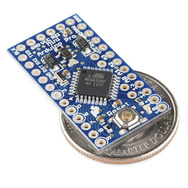
recently-acquired pro mini board as a programmer for the ATtiny, but I had fried it by accidentally connecting 12v instead of 5v to it. So I decided to build my own programmer.
My linux machine has a parallel port on-board, in the form of a 25-pin header. I didn't have a 26-wire ribbon cable to match, but I have some old 34-wire floppy ribbon cables that would fit. I plugged it onto the motherboard parallel port header, got out a breadboard, and scanned the
AVRdude documentation. I used a 5mm 3v white LED for testing the data lines (the two leads fit nicely into the .1" spacing of the ribbon cable). After some time I got it working (see video above).
A couple things I found while experimenting with AVRdude. The first is to stick with parallel port pin 10 (or one of the other 4 input lines) for the connection to pin 6 (miso) on the
ATtiny85. The parallel port input lines have pullup resistors on them(which seems to be needed on miso), while the 8 data lines do not. The other thing I figured out is that the resistors between the chip being programmed and the parallel port aren't absolutely necessary. On the sck and mosi lines the resistors don't hurt (I used 1.2KOhm since I had a handful lying around). On the miso, 1.2K didn't work - it was probably too large to pull the line down to a 0 level. A 330Ohm resistor on the miso line worked fine. I also found that reset line control is not necessary; just connect pins 1 & 4 permanently to ground (or one of the data lines that is low).
I wanted a permanent solution for a programmer, but was to lazy to solder up a circuit on a prototyping board to plug into parallel port. I thought I could plug one side of a regular dip socket into the ribbon cable header, but the pins are to short to make a connection. Then I remembered I have some old wire-wrap sockets from days gone by. I dug them up, and after one failed attempt, I made a tiny programmer for 4-pin ATtiny devices out of a 14-pin wire wrap socket:
I broke off pins 1-7, and soldered one of the broken off pins to connect pins 1-4. I soldered another broken leg between pins 4 & 9, broke off pin 12, and soldered a wire connecting pin 12 & pin 8. Pins 1-4 of the tiny85 plug into pins 1-4 of the socket, and pins 5-8 go into pins 11-14. I plugged the socket into the parallel port connector so pin 8 of the socket plugs into pin 10 of the parallel port, and pin 14 plugs into pin 4 of the parallel port. Finally, I needed to add my dipsocket programmer to /etc/avrdude.conf:
# wire wrap socket programmer
# reset line is dummy - parallel pin 6 unconnected
# reset line permanantly wired to ground
programmer
id = "dipsocket";
desc = "Wire Wrap socket STK200";
type = par;
pgmled = 3;
# buff = 4;
sck = 5;
reset = 6;
mosi = 7;
miso = 10;
;
The buff (power) line is commented out because it works just fine with parasitic power of the sck and mosi lines! The avrdude command line options are as follows:
avrdude -p t85 -c dipsocket -U flash:w:firmware.hex
Since they have the same pinout, this will work for ATtiny25 and ATtiny85 MCUs.


