Friday, December 27, 2013

Writing AVR assembler code with the Arduino IDE

Although I have written a lot of code in high-level languages like C++, I enjoy writing assember the most.  For inserting assembler code into Arduino sketches, you can read a gcc inline assembly guide.  If you have some assembly code and want to use it, there is an easier way than converting it to inline assembly; you can make it a library.

The Arduino Serial class consumes a lot of resources, and even the tiny cores serial class (TinyDebugSerial) adds overhead to the half duplex software UART code it seems to be based on.  I decided to integrate my implementation of AVR305 with an Arduino sketch.

I started by making a directory called BasicSerial in the libraries directory.  Inside I created a BasicSerial.S file for my assember code.  In order for assembler code to be callable from C++, it is necessary to follow the avr-gcc register layout and calling convention, and mark the function name global.  The TxByte function takes a single char as an argument, which gcc will put in r24.  The Arduino core uses interrupts which would interfere with the software UART timing, so interrupts are disabled at the start of TxByte and re-enabled at the end.  Here's the code:
#include <avr/io.h>
; correct for avr/io.h 0x20 port offset for io instructions
#define UART_Port (PORTB-0x20)
#define UART_Tx 0

#define bitcnt r18
#define delayArg 19

#if F_CPU == 8000000L
  #warning Using 8Mhz CPU timing 
  #define TXDELAY 21
#elif F_CPU == 16000000L
  #warning Using 16Mhz CPU timing 
  #define TXDELAY 44 
#else
  #error unrecognized F_CPU value
#endif

.global TxByte
; transmit byte in r24 - 15 instructions
; calling code must set Tx line to idle state (high) or 1st byte may be lost
; i.e. PORTB |= (1<<UART_Tx)
TxByte:
cli
        sbi UART_Port-1, UART_Tx              ; set Tx line to output
        ldi bitcnt, 10                              ; 1 start + 8 bit + 1 stop
        com r24                                    ; invert and set carry
TxLoop:
        ; 10 cycle loop + delay
        brcc tx1
        cbi UART_Port, UART_Tx                  ; transmit a 0
tx1:
        brcs TxDone
        sbi UART_Port, UART_Tx                  ; transmit a 1
TxDone:
        ldi delayArg, TXDELAY
TxDelay:
; delay (3 cycle * delayArg) -1
        dec delayArg
        brne TxDelay
        lsr r24
        dec bitcnt
        brne TxLoop
reti ; return and enable interrupts

The last thing to do is to create a header file called BasicSerial.h:
extern "C" {
void TxByte(char);
}
If the extern "C" is left out, C++ name mangling will cause a mismatch.  To use the code in the sketch, just include BasicSerial.h, and call TxByte as if it were a C function.  Here's a sample sketch:
#include <BasicSerial.h>

// sketch to test Serial

// change LEDPIN based on your schematic
#define LEDPIN  PINB1

void setup(){
  DDRB |= (1<<LEDPIN);    // set LED pin to output mode
}

void serOut(const char* str)
{
   while (*str) TxByte (*str++);
}

void loop(){
  serOut("Turning on LED\n");
  PORTB |= (1<<LEDPIN);  // turn on LED
  delay(500);            // 0.5 second delay
  PORTB &= ~(1<<LEDPIN); // turn off LED
  delay(1000);           // 1 second delay
}

Download and run the sketch, open the Serial Monitor at 115,200bps, an you should see this:

I've posted BasicSerial.zip containing BasicSerial.S and BasicSerial.h.  Have fun!

New year's update:

I've modified the code so the delay timing is calculated by a macro in BasicSerial.h.  Just modify the line:
#define BAUD_RATE 115200
BasicSerialv2.zip

Wednesday, December 4, 2013

Trimming the fat from avr-gcc code

Although writing in AVR assembly makes it easy to write programs that fit in a small codespace, writing in C and using AVR Libc is more convenient.  This article outlines how to write C code that avr-gcc will build to a minimal size.  There are a number of other guides for writing small AVR code including AVR 4027, but none of them seem to address the overhead of avr-gcc's start-up library (gcrt1).

Many people seem to be still using avr-gcc 4.3.3 as it usually generates smaller code than 4.5.3 and 4.7.  I recently tried avr-gcc 4.8.2 (linux RPM cross-avr-gcc-4.8.2-3.2) , and for the program I use here, it generates even smaller code than 4.3.3.

The test program uses the ATtiny85's internal temperature sensor and flashes the temperature using a LED.  When compiled using -Os it results in a 274-byte program:
avr-size temperature
   text    data     bss     dec     hex filename
    274       0       0     274     112 temperature.bu
With avr-gcc 4.8.2 that drops to 240 bytes:
 avr-size temperature-4.8
   text    data     bss     dec     hex filename
    240       0       0     240      f0 temperature-4.8

The difference is primarily in the startup files linked to the code.  Disassembling the code with avr-objdump -d shows the reset vector contains a jump to a function called __ctors_end:
   0:   0e c0           rjmp  .+28      ; 0x1e <__ctors_end>
0000001e <__ctors_end>:
  1e:   11 24           eor     r1, r1
  20:   1f be           out     0x3f, r1        ; 63
  22:   cf e5           ldi     r28, 0x5F       ; 95
  24:   d2 e0           ldi     r29, 0x02       ; 2
  26:   de bf           out     0x3e, r29       ; 62
  28:   cd bf           out     0x3d, r28       ; 61

The function __ctors_end falls into __do_copy_data, which falls into __do_clear_bss before an rcall to main followed by an rjmp to _exit.  In total it's about 50 bytes of code before calling main.  With avr-gcc 4.8.2, the only code before main is __ctors_end, or 16 bytes of what would seem to be overhead.

Before trying to cut out __ctors_end, I wanted to make sure the code in __ctors_end is really overhead that can be safely removed.  The first two lines clear SREG.  Section 8.1 of the ATtinyX5 datasheet states, "During reset, all I/O Registers are set to their initial values, and the program starts execution from the Reset Vector."  The datasheet also indicates it's initial value is 0, so the first two lines can go.  The last 4 lines set the stack pointer (SPL and SPH) to RAMEND, which section 4.6 of the datasheet indicates is their initial value.  So it is safe to get rid of __ctors_end and jump straight to main from the reset vector, for a savings of 16 bytes.

Another 30 bytes of data is used for the interrupt vector table (and even more than 30 bytes on the ATmega series MCUs).  Section 9.1 of the datasheet states, "If the program never enables an interrupt source, the Interrupt Vectors are not used, and regular program code can be placed at these locations."  My temperature blinking program doesn't use interrupts so more space can be saved by getting rid of the interrupt table.

The way to tell avr-gcc not to link in the startup code is -nostartfiles.  If that is all you do with your C code, then avr-gcc will stick the first object file at address 0 (the reset vector).  To ensure the reset vector contains a jump to main I wrote a small assembly program (crt1.S).  I this custom startup code instead of gcrt1 included with the compiler libraries.  The code isn't long, so I'll include it inline:
.org 0x0000
__vectors:
rjmp main

Compile it (avr-gcc -c crt1.S), and link it with your C code.  For compiling temperature.c here's the command line I used, including a couple of extra flags helpful for generating small code:
avr-gcc -mmcu=attiny85 -Os -fno-inline-small-functions -mrelax -nostartfiles crt1.o    temperature.c   -o temperature

The resulting program is 190 bytes, saving 84 bytes vs. avr-gcc 4.3.3 or 50 bytes vs. 4.8.2:
avr-size temperature
   text    data     bss     dec     hex filename
    190       0       0     190      be temperature

Note that many virtual bootloaders for the ATtiny MCUs will cause problems with this technique as they tend to assume application code doesn't start until after the interrupt vector table.  MCUs with hardware bootloader support (i.e. the ATmega series) will not have problems.  Picoboot, the bootloader I am writing, will only assume the reset vector contains an rjmp to the start of application code and therefore will work with my custom crt1.o.

Monday, November 25, 2013

Testing IPv6 on Windows

I recently decided to test IPv6 on Windows 7.  It has Teredo support, which will use tunnelbroker.net's free service and assign an ipv6 host address to the PC.  I found a few sites with instructions on how to configure teredo including this one.  I was able to get it to work a bit, and tested it with test-ipv6.com. However I wasn't able to get it to work consistently, and I could never get windows to prefer teredo ipv6 connections over ipv4.  I don't know if the inconsistency was an issue with teredo or with the tunnel servers, so I decided to try something else.

While searching for information on ipv6 setup on Windows, I read about the Freenet6 Tunnelbroker.  I downloaded and installed the client software.  I clicked "connect" on the gogoClient utility, and in a couple seconds had a working tunnel:

It also prioritized ipv6 over ipv4, so when I went to sites like lg.he.net, the connection used ipv6.  The last thing I wanted to try was to try ipv6 only.  I couldn't completely disable ipv4, since it is needed for the tunnel.  So what I did was add a static route to the tunnel endpoint:
route add 81.171.72.12/32 192.168.1.1
and then I deleted the ipv4 default route:
route delete 0.0.0.0
I made sure I couldn't reach ipv4 sites by trying to ping 8.8.8.8 (which failed as expected).  Google sites including youtube were ipv6 reachable.  Microsoft sites like bing.com were not (no DNS AAAA records).  Facebook was ipv6 reachable, as was the main yahoo.com site, but not yahoo mail.  Unfortunately many sites I frequent such as hackaday.com and digitimes.com have no ipv6 connectivity, so I won't be going ipv6 only any time soon.

Wednesday, September 18, 2013

clone PL-2303HX USB to TTL serial adapters

USB-TTL modules using the PL-2303HX chip are the cheapest ones around ($1.40 from Fasttech).  The chip has a built-in 3.3v regulator, so the modules can supply both 5v and 3.3v power.  Drivers for them are included in the Linux kernel and in Mac OSX too.

Apparently the chip has been cloned, and as a result Prolific updated their Windows drivers to detect the clone chips and fail.  If you are getting "Error Code 10", the module will work with earlier versions of the driver.

For Windows 7 64-bit, this version works.  Unzip the file, then in device manager select device properties, update driver, have disk.  For 32-bit windows, this version works fine.

Besides its intended use, I have used it as a breadboard 3.3 & 5v power supply with a USB extension cable to a 5v USB power supply (or a computer USB port).

I also find the adapters handy as a simple voltage tester.  The T and R LEDs light up when pulled to ground, so I'll attach them to MCU pins to check for pulses.

Sunday, September 8, 2013

Control 6 LEDs with 2 pins using Gracieplexing

In my last post I explained Gracieplexing and demonstrated how to control 2 LEDs with 1 pin, an explained how 2 pins could be used to control up to 8 LEDs.  In this post I'll explain how to control 6 LEDs, and later do a third posting about a circuit to control the full 8 LEDs along with C code for Arduino-compatible MCUs to manipulate the 8 LEDs.

The following matrix describes how the state of the 2 MCU pins will map to the LEDs:
Using two pins independently us to control LEDs 1 through 4; the extra complexity is in controlling LED 5 and 6.  By wiring the extra 2 LEDs in opposite polarity between the two MCU pins, when one pin is high and the other low we will turn on LED5, and LED will turn when the pin polarities are flipped.  If we stopped there, we would have a problem though.  Turning on LED5 would also turn on LED3.  We can solve that problem by adding a standard (~0.6v) diode in series with LED3.  Using red LEDs with a Vf of 1.8v, a total of 2.4v will be required to turn on LED3, but when LED5 is on there will only be 1.8v.  However when the cathode of LED5 is not pulled low, the voltage will rise and turn on LED3.  In addition to the schematic I've done a Fritzing breadboard layout for connecting to an MCU.
And here's a video demonstration on a breadboard:

Sunday, August 25, 2013

Gracieplexing - a new method for LED multiplexing

Controlling LEDs is one common use for small microcontrollers.  Multiplexing techniques can be to control the maximum number of LEDs with the minimum number of MCU pins.  One popular technique is Charlieplexing, which is an improvement over basic multiplexing which allows you to control (1/2 n)^2 LEDs with n pins. With basic multiplexing 6 pins would allow you to control a 3x3 matrix for a total of 9 LEDs.  With Charlieplexing you can control 6 x (6-1) = 30 LEDs, but that is far from optimal.  With a technique I'll call Gracieplexing, you could theoretically control 728 LEDs with 6 pins, or n^3 - 1 LEDs with n pins.  So starting with 1 pin you can control 2 LEDs:

So how does this work? Well basic math tells us when we have n binary bits we can represent 2^n states.  If our output pin could only be in the high or low state, with one pin we would only have 2 states (1 LED that is on or off).  With tri-state MCU outputs we can represent 3^n states with n pins.  In the circuit diagram above when the pin output is high, the bottom LED will light up.  When it is low, the top LED will light up, and when it is high-Z, both LEDs will be off.  Vcc is less than 2x the forward voltage of the LEDs, so they don't light up for high-Z.

Below is a video demonstrating the technique on a breadboard.  Gracieplexing starts getting complicated when you have more than one pin, and so far I haven't figured a way to control 7 LEDs with 2 pins without adding a couple transistors to the circuit.  Even without using transistors, you can still control more LEDs than with Charlieplexing, and I'll go over the details of Gracieplexing with more pins in part 2.

Saturday, August 17, 2013

tiny programmer for the ATtiny85

The ATtiny85 MCUs I ordered from tayda arrived earlier this week, and I wanted to start programming them.  I had considered using my recently-acquired pro mini board as a programmer for the ATtiny, but I had fried it by accidentally connecting 12v instead of 5v to it.  So I decided to build my own programmer.

My linux machine has a parallel port on-board, in the form of a 25-pin header.  I didn't have a 26-wire ribbon cable to match, but I have some old 34-wire floppy ribbon cables that would fit.  I plugged it onto the motherboard parallel port header, got out a breadboard, and scanned the AVRdude documentation.  I used a 5mm 3v white LED for testing the data lines (the two leads fit nicely into the .1" spacing of the ribbon cable).  After some time I got it working (see video above).

A couple things I found while experimenting with AVRdude.  The first is to stick with parallel port pin 10 (or one of the other 4 input lines) for the connection to pin 6 (miso) on the ATtiny85.  The parallel port input lines have pullup resistors on them(which seems to be needed on miso), while the 8 data lines do not.  The other thing I figured out is that the resistors between the chip being programmed and the parallel port aren't absolutely necessary.  On the sck and mosi lines the resistors don't hurt (I used 1.2KOhm since I had a handful lying around).  On the miso, 1.2K didn't work - it was probably too large to pull the line down to a 0 level.  A 330Ohm resistor on the miso line worked fine.  I also found that reset line control is not necessary; just connect pins 1 & 4 permanently to ground (or one of the data lines that is low).

I wanted a permanent solution for a programmer, but was to lazy to solder up a circuit on a prototyping board to plug into parallel port.  I thought I could plug one side of a regular dip socket into the ribbon cable header, but the pins are to short to make a connection.  Then I remembered I have some old wire-wrap sockets from days gone by.  I dug them up, and after one failed attempt, I made a tiny programmer for 4-pin ATtiny devices out of a 14-pin wire wrap socket:

I broke off pins 1-7, and soldered one of the broken off pins to connect pins 1-4.  I soldered another broken leg between pins 4 & 9, broke off pin 12, and soldered a wire connecting pin 12 & pin 8.  Pins 1-4 of the tiny85 plug into pins 1-4 of the socket, and pins 5-8 go into pins 11-14.  I plugged the socket into the parallel port connector so pin 8 of the socket plugs into pin 10 of the parallel port, and pin 14 plugs into pin 4 of the parallel port.  Finally, I needed to add my dipsocket programmer to /etc/avrdude.conf:
# wire wrap socket programmer
# reset line is dummy - parallel pin 6 unconnected
# reset line permanantly wired to ground
programmer
  id    = "dipsocket";
  desc  = "Wire Wrap socket STK200";
  type  = par;
  pgmled = 3;
#  buff  = 4;
  sck   = 5;
  reset = 6;
  mosi  = 7;
  miso  = 10;
;


The buff (power) line is commented out because it works just fine with parasitic power of the sck and mosi lines!  The avrdude command line options are as follows:
avrdude -p t85 -c dipsocket -U flash:w:firmware.hex

Since they have the same pinout, this will work for ATtiny25 and ATtiny85 MCUs.

Wednesday, August 7, 2013

Getting started with Arduino & AVR

It seems projects using embedded micro-controllers are quite popular, with many references to them on Hack a Day and instructables.  I decided to take the plunge.

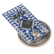
I'm cheap, so spending $25 for an Arduino UNO was out of the question.  For that price, my money would be better spent on a Raspberry Pi.  A UNO clone for ~$10, or a DigiSpark ($11.95 shipped) was looking more attractive.  I decided to order a variant of Sparkfun's Pro Mini from Fasttech for $5.25.
I could have gone for an even cheaper option of a bare ATtiny85 (and did order a couple of these as well), but wanted a more complete functioning Arduino-compatible board to start off with.  The AVR CPUs on the Arduino boards have bootloader firmware pre-installed, making programming a bit simpler.  LadyAda has a tutorial on AVR programming, so I won't duplicate it.  The bootloader uses serial TTL (0-5V) to communicate with the development host - both for downloading code and for your code to write to the host.  Comm ports on a computer (RS232) typically use -12 to +12V, so I'll either need to build a simple serial port adapter, or buy a USB to TTL serial adapter.  Since most new computers don't have serial ports, I'll probably go the USB route.

I'm planning to do my development in C under Linux.  That requires installing avr-gcc and binutils.  The package I installed are cross-avr-gcc, cross-avr-binutils, and avrdude.  The Arduino IDE is available for Linux, however I'm comfortable with vi and a shell prompt.  The Arduino libraries are in C++, and given the limited code space I'll be dealing with (8K in the ATtiny85), I want the code size efficiency of C.  Arduino Lite provides the basic functions of the Arduino library in less than half the code size.

Thursday, August 1, 2013

Home phone service over cellular

My wife had considered getting rid of her home phone service and go with just cellular, but prefers the ergonomics of a portable handset for long phone calls.  When I recently was switching her mobile service from Telus to Roger/Fido, the fido agent offered their wireless home phone service for $10/mth.  He also offered $50 in credits after two months to offset the $30 one-time cost of the adapter.  We decided to go for it.

Before the phone line adapter arrived, we received a shipping confirmation from fido which indicated the adapter is a ZTE WF720 which AT&T wireless has been using for their service in the US for the past year.

The adapter arrived by UPS, and included a fido 3G LTE sim.  I tried the sim in my unlocked phone, but it is pin locked (until I figure out how to crack it!).  So I installed it in the phone adapter (in the battery slot compartment), plugged in the battery & power, plugged in a phone, and got dialtone.  The sim was pre-programed with a temporary number to use while we wait to port the land line.

The sound quality is typical of a gsm codec - adequate but not as good as a land line.  For the heck of it I tried sending a fax, and it negotiated with the receiving side but failed on page 1.  So it's fine for voice, but not for data.  For the price, I can't complain.